Schematic Circuit Calculator
Calculate circuit parameters such as resonant frequency, filter cutoff frequency, divider ratio, capacitor charging time, resistor ratio, operational amplifier parameters and coil inductance in schematic and PCB design. The calculation results can be applied to component attributes or design rules.
For the trace width, power dissipation and other calculators on the PCB, see PCB Circuit Calculator.
Entry
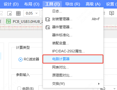
Top Menu - Tools - Circuit Calculator
Window Overview
The Circuit Calculator window has the list of calculator categories on the left and the parameter input and calculation result area on the right. The window size is fixed to the largest area among all calculators, and opening it does not affect canvas operations.
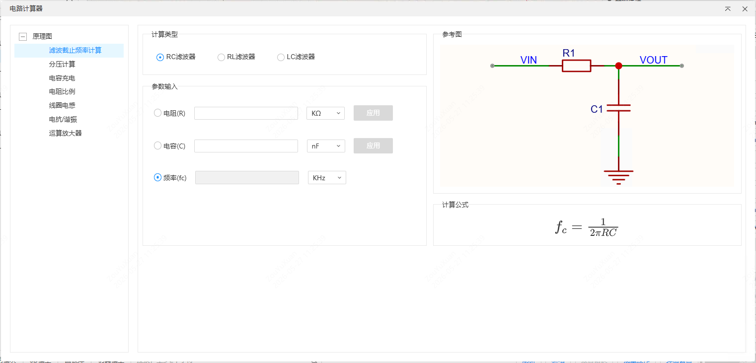
- Category switching: the list on the left contains two main categories, Schematic and PCB. The matching category is displayed automatically according to the type of the page currently open (schematic/PCB), and the window closes automatically when you switch the page type.
- Input boxes: use the scroll wheel to fine-tune values, and switch the unit on the right. Calculation results keep three decimal places (one decimal place for power dissipation calculations), and the unit switches adaptively (for example, 1000 Hz is automatically displayed as 1 KHz).
- Radio buttons: most calculators let you specify the calculation target with a radio button — the selected item is the result to be solved (its input box is not editable), and the unselected items are the known conditions (which must be entered manually). When all known conditions are valid, the result is calculated and updated in real time.
- Apply button: the button is clickable when the input boxes have values (otherwise it is not clickable). After clicking, the window is hidden and a "Please select a component" tooltip follows the mouse; click a target component on the canvas to assign the result to the component's Value attribute (if it has no Value attribute, one is added). Right-click to exit apply mode and display the window again. In read-only mode the Apply button cannot be operated.
Resonance Calculation
Used for wireless transmit/receive circuits, RFID card readers, resonant soft switching in switching power supplies and similar scenarios, to calculate capacitive reactance, inductive reactance and resonant frequency.
Normal Mode
By default the "Resonance Mode" checkbox is not checked, the capacitance, inductance and frequency input boxes are all editable, and each is calculated independently:
- Enter the capacitance C and the frequency f to calculate the capacitive reactance Xc
- Enter the inductance L and the frequency f to calculate the inductive reactance Xl
- In this mode the resonant frequency is displayed as "-"
Resonance Mode
After the "Resonance Mode" checkbox is checked, the circuit is in a resonant state (Xc = Xl), and the capacitance, inductance and frequency input boxes are interlocked:
- Select a radio button to the right of the capacitance, inductance or frequency to specify it as the calculation target (that input box is not editable)
- Enter valid values for the other two as the known conditions
- The system calculates the selected target value in real time, and the capacitive reactance, inductive reactance and resonant frequency at the bottom are refreshed at the same time
Filter Cutoff Frequency Calculation
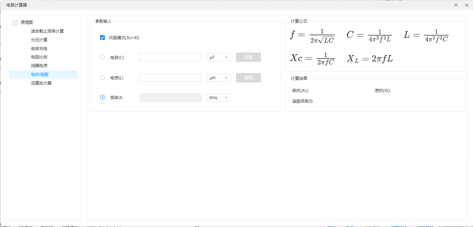
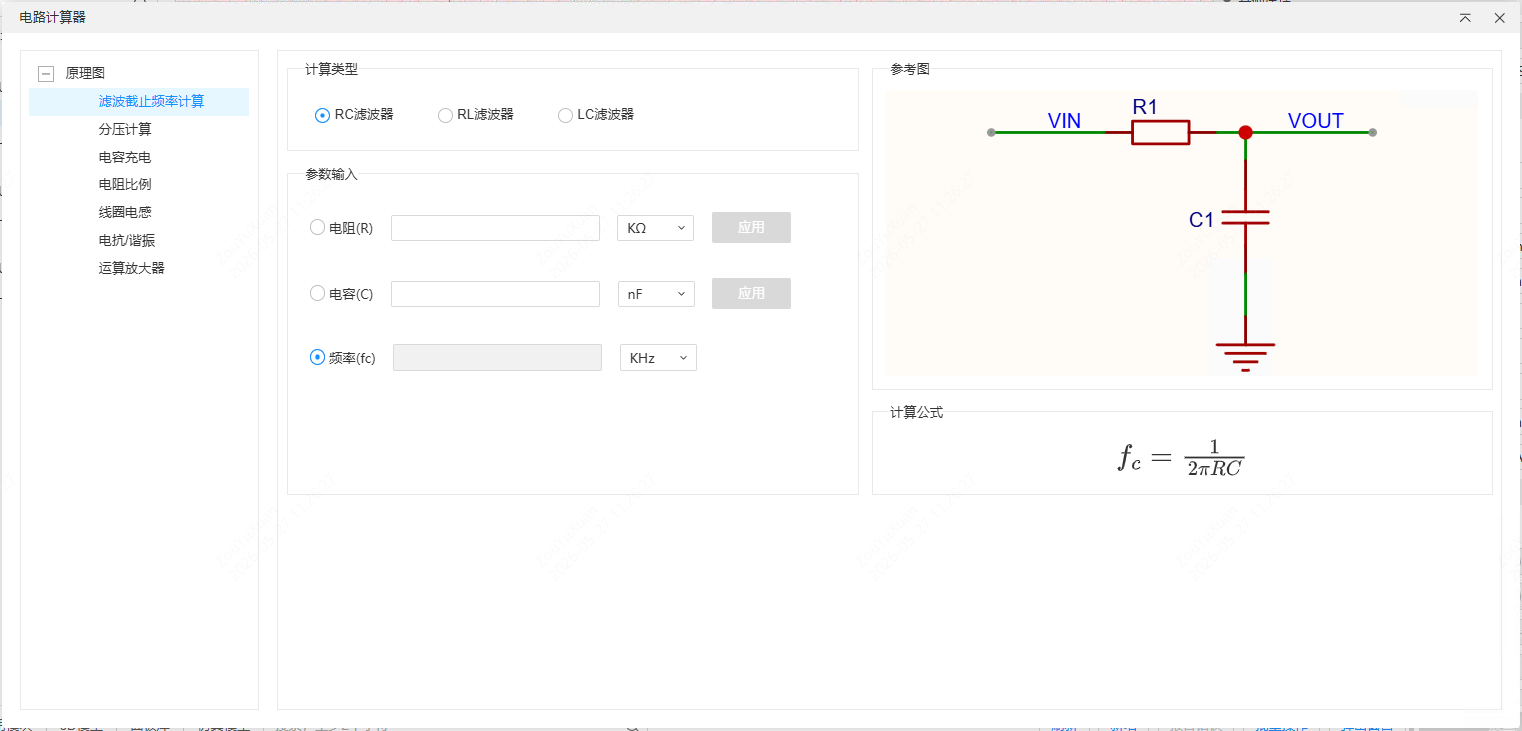
Used for audio processing, power supply decoupling, sensor signal smoothing and similar scenarios, to calculate the filter cutoff frequency.
- Select the filter type (single choice): RC Filter (default), RL Filter or LC Filter
- For each filter type, the corresponding resistance/capacitance/inductance input boxes and reference diagram are displayed
- Select the radio button to the left of any input box to specify it as the calculation target (not editable), and enter the known conditions in the remaining input boxes
- When all known conditions are valid, the selected target value is calculated and updated in real time
When you switch the filter type, the frequency input box is automatically selected as the calculation target and cleared.
Voltage Divider
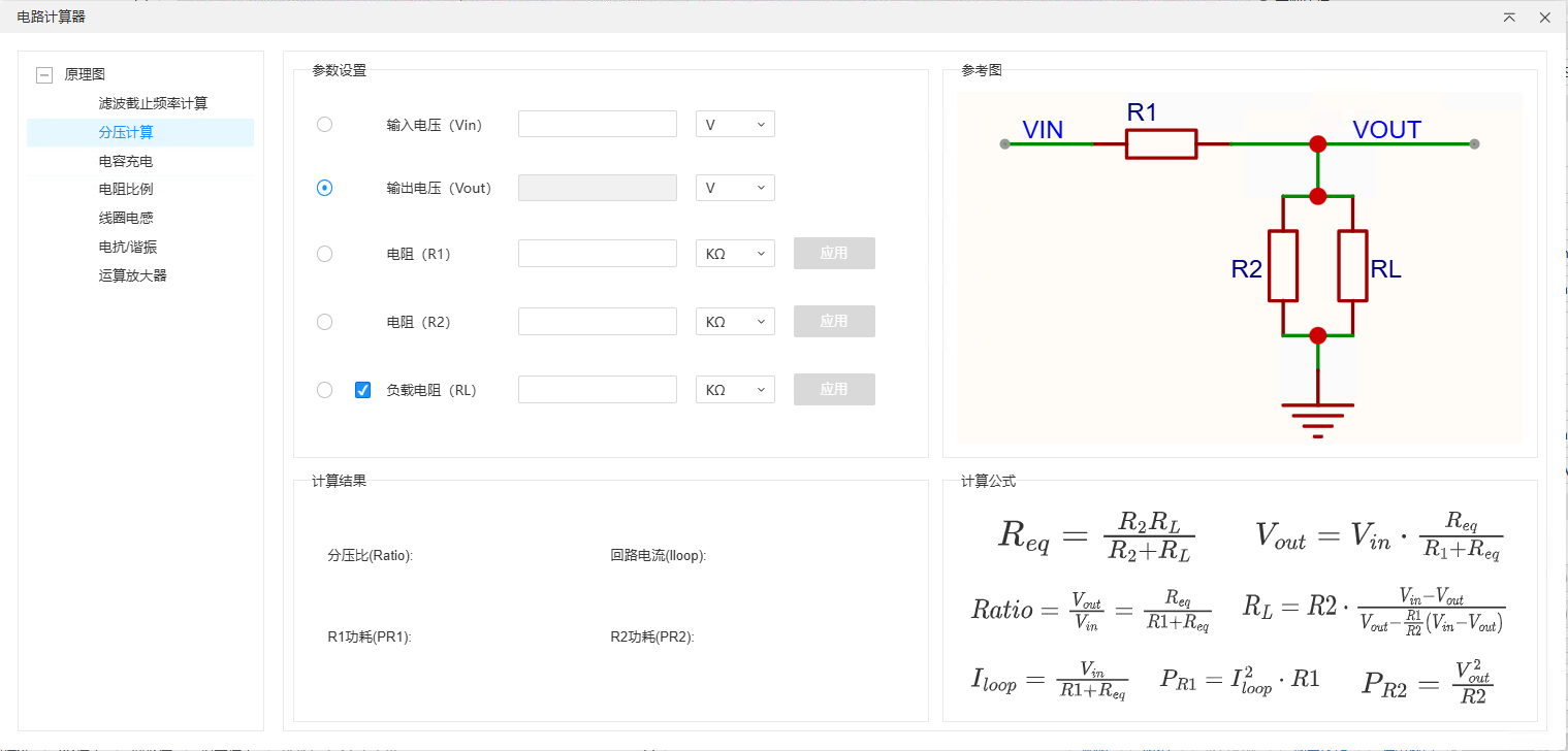
Used for battery voltage detection (ADC sampling), LDO feedback resistor setting, level shifting and similar scenarios.
- Enter Vin, R1 and R2, then select the radio button to the right of any input box to specify the calculation target
- When all known conditions are valid, the target value is calculated in real time and the results at the bottom are updated at the same time: Divider Ratio, Circuit Current, R1 power dissipation, R2 power dissipation
- You can check the "Load Resistor RL" checkbox. Once enabled:
- The reference diagram switches to "with load" mode
- The RL input box becomes editable, and can be selected with a radio button as the calculation target
- The results at the bottom take the load into account at the same time
When you uncheck the load resistor, if RL is currently selected the selection automatically switches to Vout.
Capacitor Charge Calculation
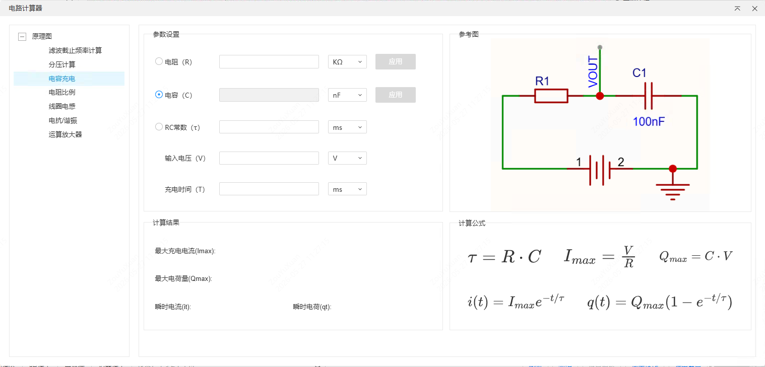
Used for RC circuit time constant calculation and transient response analysis.
- Each of the resistance, capacitance and RC constant input boxes has a radio button on its left; select one as the calculation target
- The input voltage and charging time do not take part in the single choice and are always editable; they are used for the calculation of the results at the bottom
- After you change any known condition, the target value is calculated in real time and the results at the bottom are updated: maximum charging current, Max Stored Charge, Instantaneous Current, instantaneous charge
Resistor Ratio Calculation
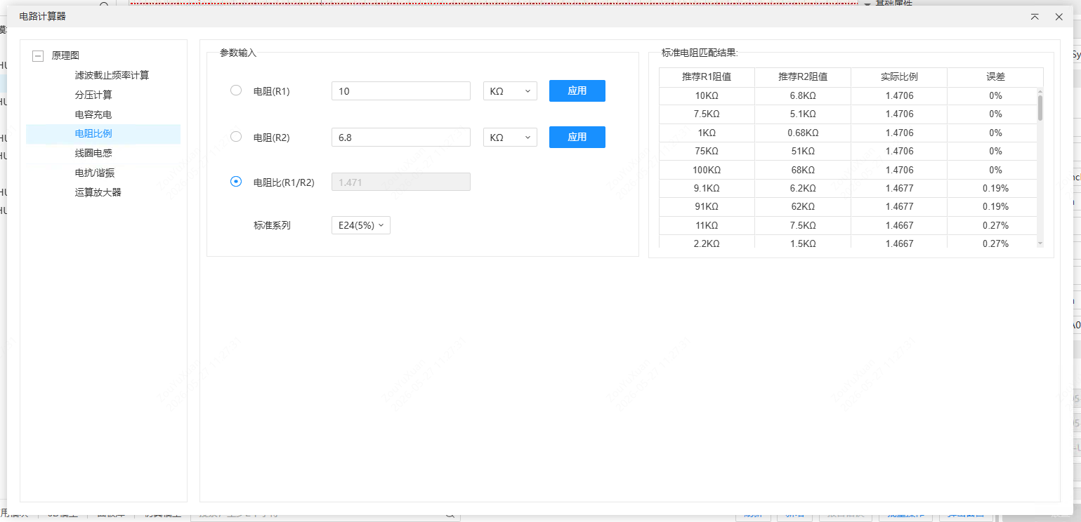
Used for operational amplifier gain setting, DC-DC feedback network design and voltage divider circuit design, to find the two resistors closest to the target ratio in a standard resistor series.
- Enter R1, R2 or the resistor ratio, then select the radio button to the left of any input box to specify the calculation target
- Select the tolerance class from the "Standard Series" drop-down menu: E6 (20%), E12 (10%), E24 (5%) (default), E48 (2%), E96 (1%), E192 (0.1%)
- The system calculates in real time and shows the Standard Resistor Matching results in the table on the right:
- Sorted by Deviation from smallest to largest; when the deviations are the same, sorted by resistance deviation
- Shows the R1, R2, actual ratio and Deviation of each matching group
- A scrollbar appears when there are more than 5 groups of data
When you switch the standard series, the matching results are refreshed immediately. Calculation results keep three decimal places, and deviations keep four decimal places.
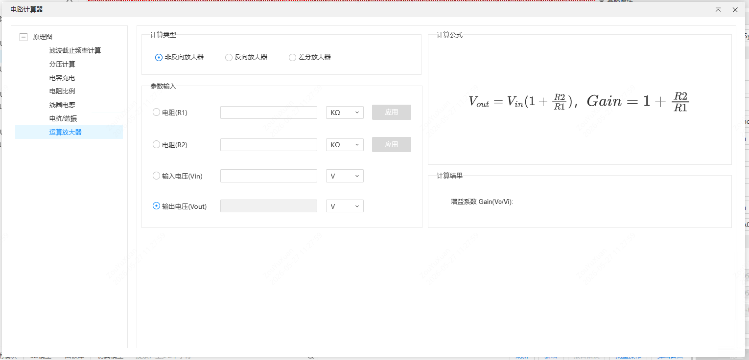
Operational Amplifier Parameter Calculation
Used for signal amplification and sensor interface circuit design.
- Select the amplifier type (single choice): Non-Inverting Amplifier (default), Inverting Amplifier or Differential Amplifier
- Enter R1, R2, Vin and Vout, then select the radio button to the right of any input box to specify the calculation target
- When all known conditions are valid, the target value is calculated in real time, and the Voltage Gain is shown at the bottom
Validation rules for each type:
- Non-Inverting Amplifier: if |Vout| < |Vin|, the parameters are reported as invalid
- Inverting Amplifier: if Vout and Vin have the same sign, the parameters are reported as invalid
- Differential Amplifier: the resistor matching mode is used by default (R3=R1, R4=R2), and Vin represents the differential mode input voltage
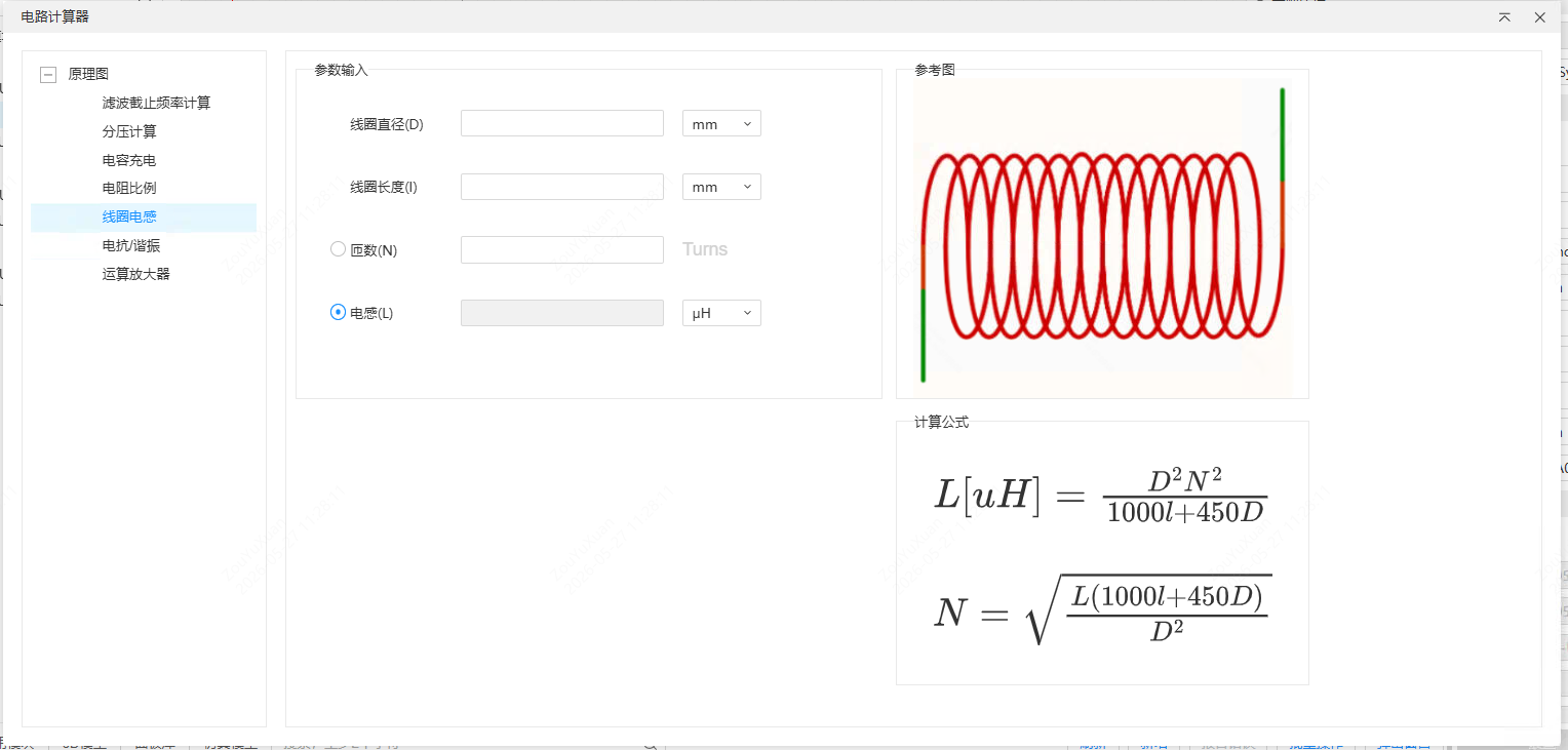
Coil Inductance Calculation
Used for RF circuit design, home-made air-core coils, filter inductance parameter estimation and antenna matching networks.
- Enter the coil diameter D and the coil length l, then select the radio button to the right of the inductance L or the Number of Turns N to specify the calculation target
- When all known conditions are valid, the target value is calculated in real time
The coil diameter and length are in mm by default, and the calculated Number of Turns keeps one decimal place.