

Polyline Arrow Styles
When drawing a polyline in the schematic and symbol editors, you can set the arrow styles of the start point and the end point, to indicate signal flow, data transfer, annotation pointing, and so on.
Entry
Top Menu - Place - Polyline, right property panel - Start Shape / End Shape
You can also enter it from the polyline button in the top toolbar.
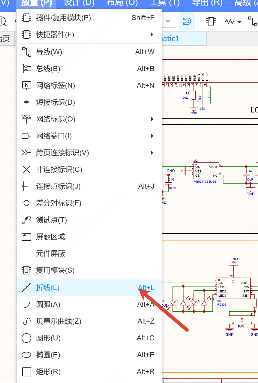
Placing Arrows
- Select Polyline from the menu or the toolbar
- Move the mouse onto the canvas; a cross cursor appears and an arrow icon is shown in the first quadrant
- Left-click to set the start point, move the mouse to preview the pending segment, and left-click again to add an intermediate point
- Several left-clicks add more intermediate points; right-click to finish drawing
During placement, cursor snapping follows the default grid size setting; press Alt to use the Alt snap size.
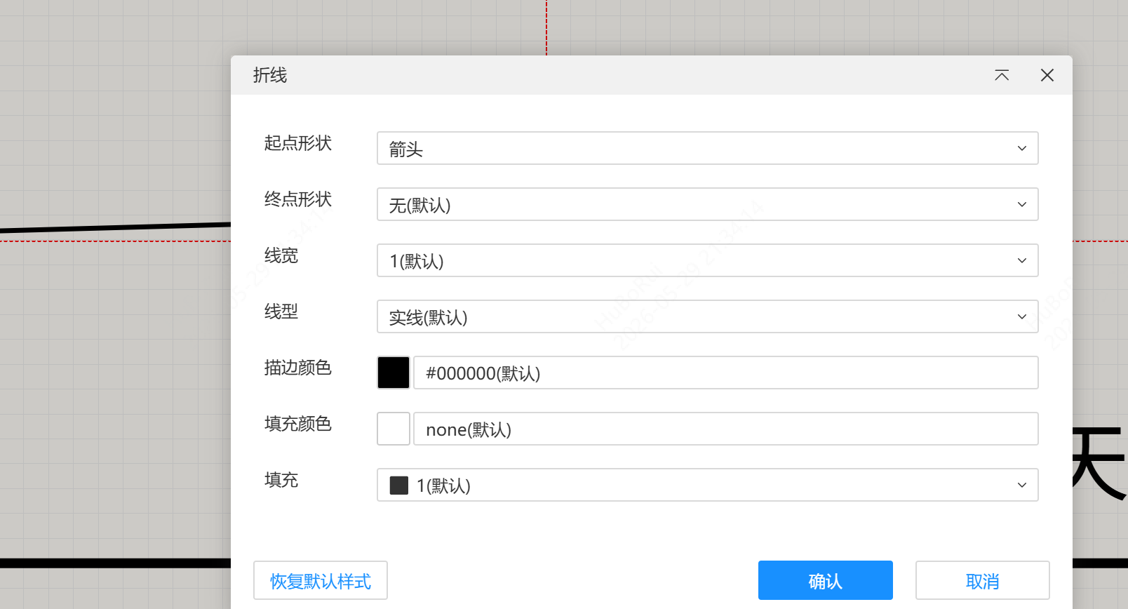
Modifying the Style with Tab
Press Tab while placing a polyline to open the arrow property pop-up window, where you can set the start shape and the end shape.
Modifying Properties
Select a polyline that has already been drawn, then choose a style from the Start Shape and End Shape drop-down lists in the right property panel. The options are: None, Arrow, Solid Arrow, Tail, Swallowtail Arrow, Circle, Square and Diamond. Both default to "None".
The arrow direction follows the drawing direction, and its size follows the line width.
Adjusting Arrows
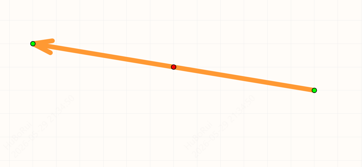
Click an arrow to select it; its end points turn green and become draggable, and the midpoints between the end points turn red. After you drag a midpoint, that point becomes a new end point and a new midpoint is generated automatically.
Arrows can be grouped with other primitives.
Import and Export
- Import arrow styles from Altium schematics and schematic libraries
- Import arrows from PADS Pro schematics and schematic libraries
- Altium export supports exporting arrows
- Polyline data from older versions automatically gains arrow attributes when opened in a newer version, with the default value "None"