V1.4.x Update Notes
Schematic
- The default grid of schematic diagram is set to 0.05, and ALT grid is supported (ALT will follow the set grid when moving primitives). The default line width is to follow the zoom change, and the default setting needs to be restored manually

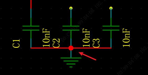
- Vertical wires are automatically displayed vertically when setting the network name
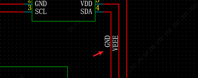
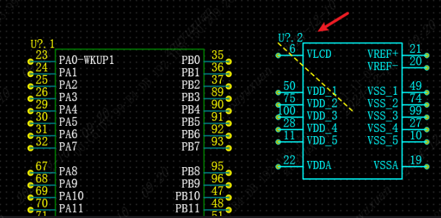
- Multi-part component bit numbers followed by stitching serial numbers are displayed on the canvas
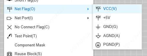
- Add a special symbol entry under the placement menu
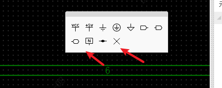
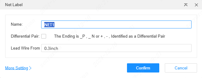
- Float toolbar to increase placement of network labels and non-links; Press TAB to change the order when placing network labels
Support uploading BOM to core manager and placing orders with one click
Support pin to link multiple wires, support pin overlap pin, please in "design - Design rules - Restore default" first.
Support the creation of the associated device while creating the symbol
Wire the Name support drop-down in the properties panel to select the network name of the current schematic
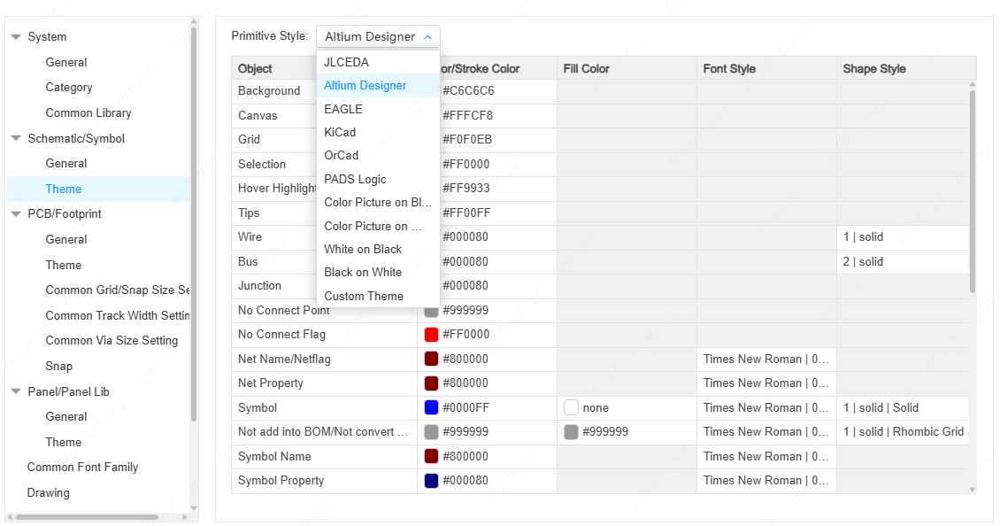
New schematic theme switch, support multiple EDA styles
- Open a symbol or package if there are no associated devices will prompt the association
-Optimize the interaction of the left tree and add component classification under the network Tab
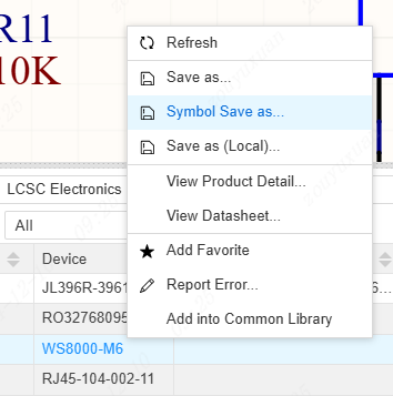
- Support saving symbols and packages when saving devices as
Support for exporting schematic diagrams of the entire project
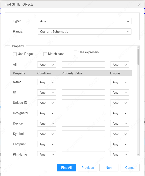
Support to find similar objects by right clicking on the canvas or in the edit menu, CTRL+SHIFT+F
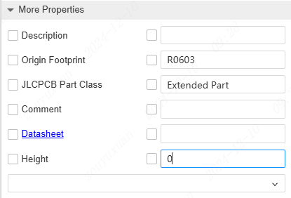
- Support adding attributes to device descriptions when placing devices
- The bottom component library supports batch deletion and batch modification classification

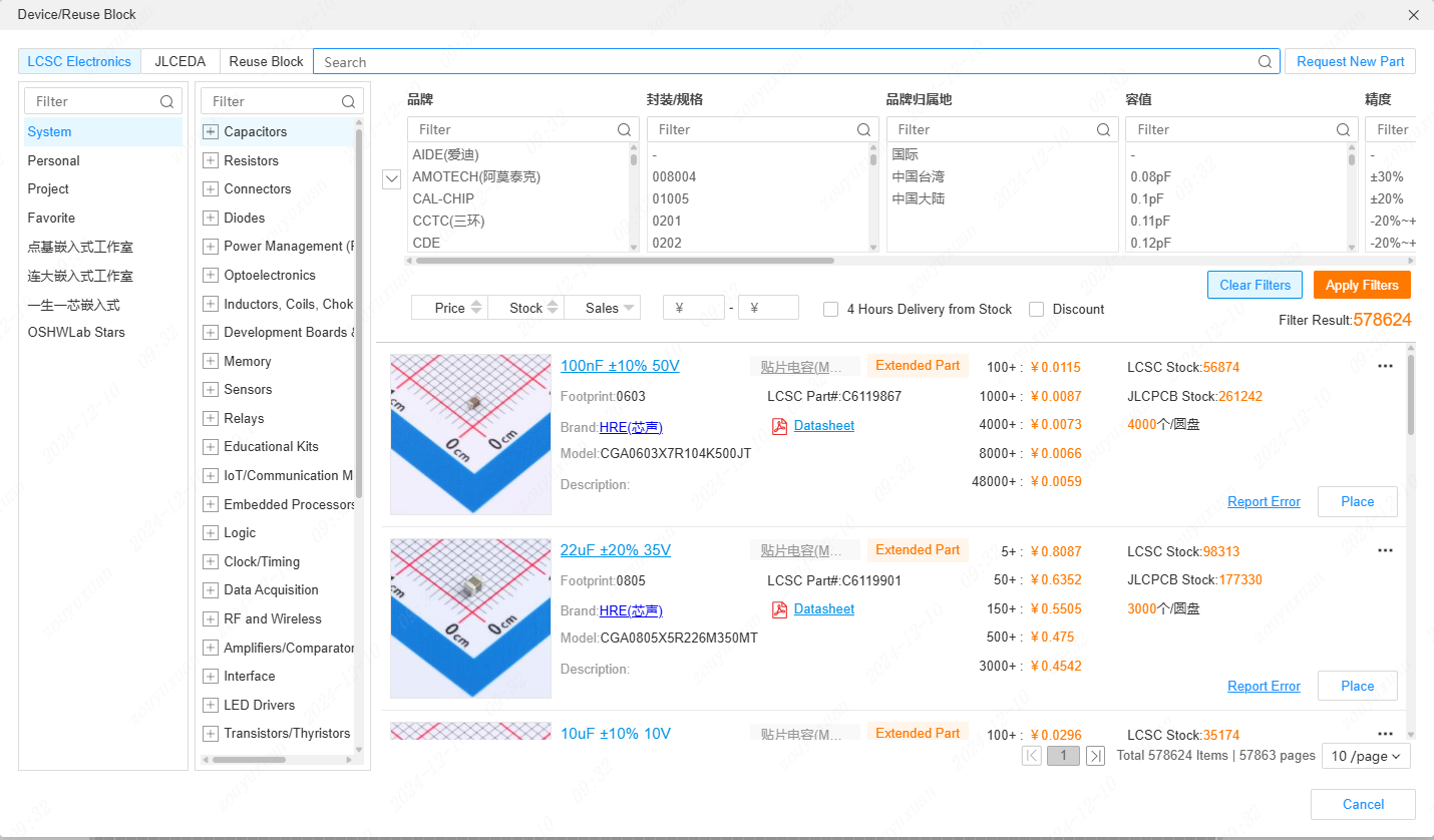
- Support new device placement dialog box, switch details list and table list, shortcut key SHIFT+F, support to display store inventory and patch inventory, support to display ladder price, view specifications, etc
- Design rule dialog box to add instant validation function. The design rule level has been adjusted, and it is recommended to restore the default rule.
-Design rules to support detection of dangling pins
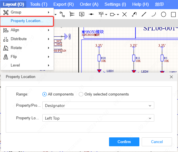
- Support to set the position of schematic element properties in the Layout menu - Properties position
- The properties panel distinguishes between base and custom property folds
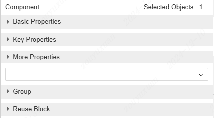
- Right click menu of components to view specifications and view product details; The properties panel allows you to open a specification by clicking directly on the specification link

- Support toggle of wire click selection type, single segment selection or whole segment selection
PCB
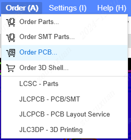
- Support one click to order PCB
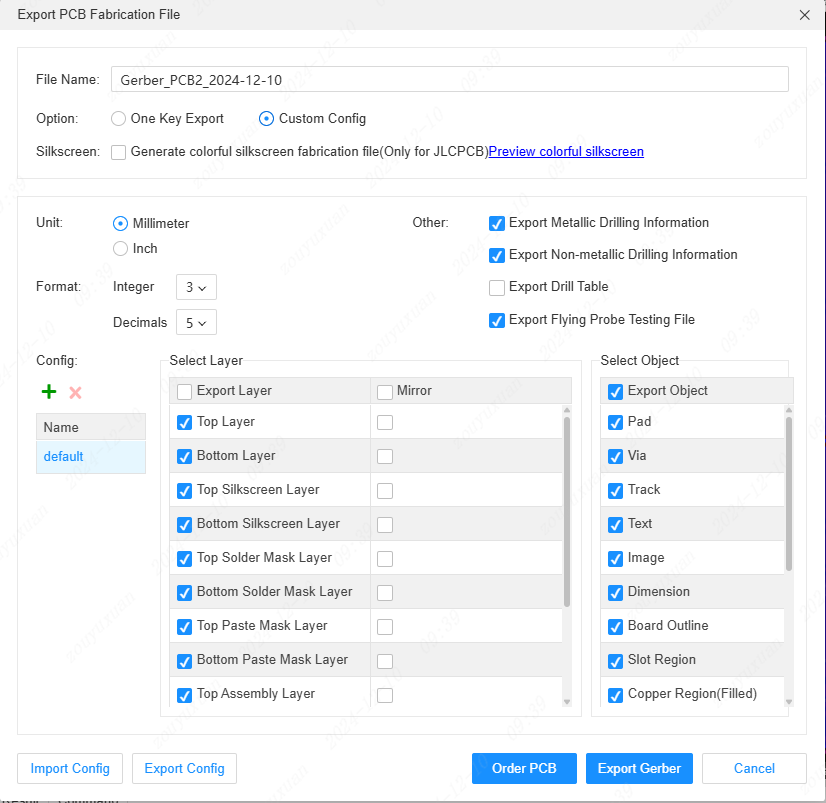
- Support for exporting Gerber to select custom output layers and primitives, and format parameters
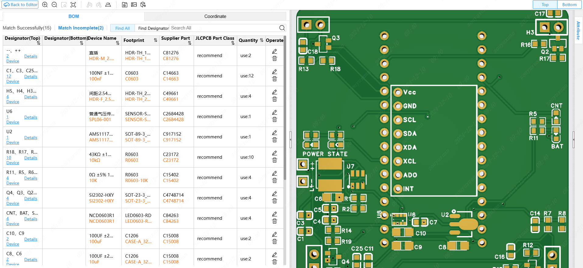
Added BOM matching tool in Tools menu (the matched BOM is only valid at that time), support exporting 3D images and 3D files
Add welding AIDS to the Tools menu
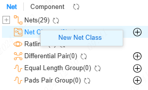
- Optimize the network class Settings dialog
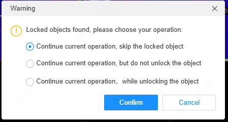
- Support for selecting action types when manipulating locked primitives
- Support flipping when moving, pasting
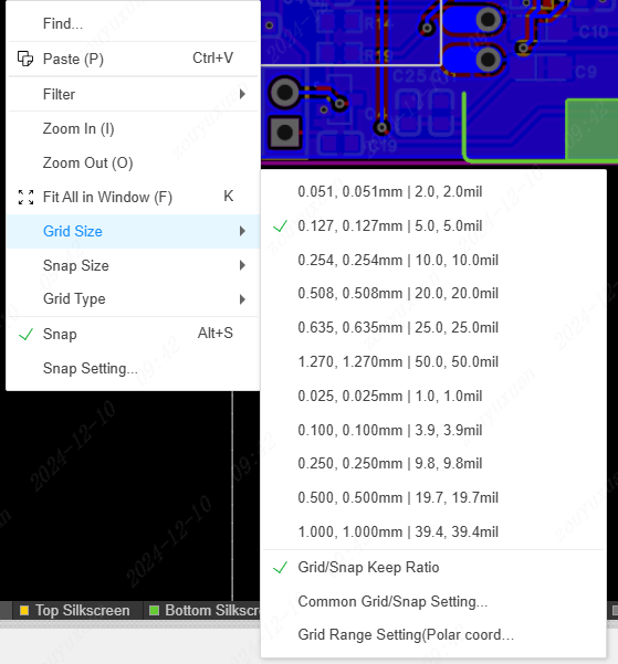
- Optimize grid, vias size, wire width right click list display styles
-PCB Settings add the option to float primitives highlighting networks and highlighting objects
- The properties panel supports switching rules and editing rules
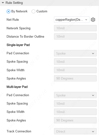
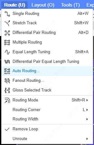
- Support for autowiring, and autowiring Settings (first release, continuous improvement)
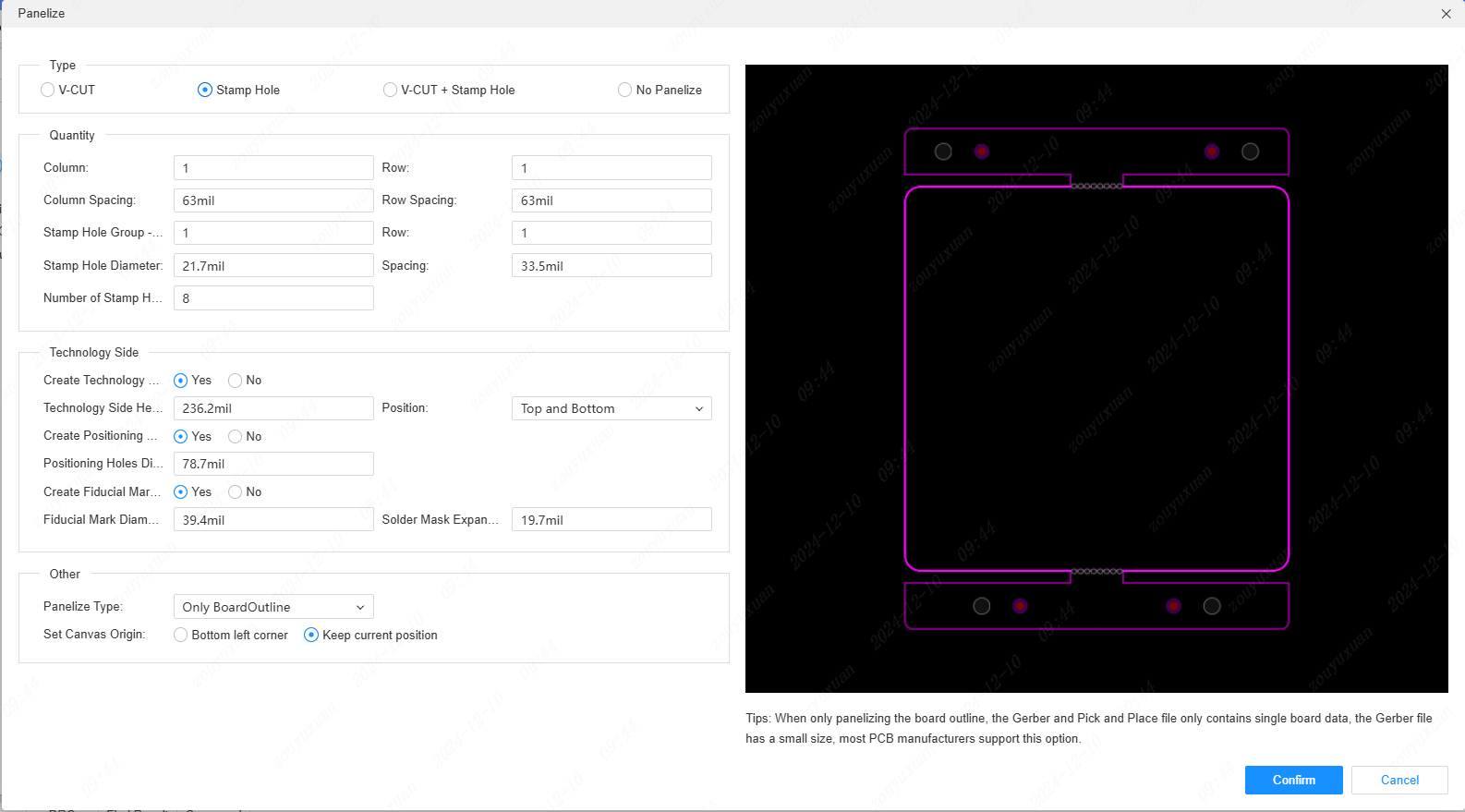
- Support the Mosaic function, under the Tools menu
Support interactive switching by clicking wire selection; Determine interactive switching of wire segments during rendering; Interactive hole-punching switching during wiring; Support the end of the meta drawing interactive switch
Support ALT movement of preset grids
Optimize the left network tree
Add test point shortcut P
Optimized adsorption only targets the currently active layer and the graph primitives with the network
Equal length network group classification is added to the left network tree
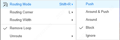
Support routing surround, toggle in routing menu
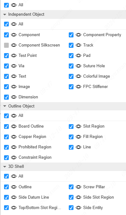
- Support for saving layer switching and filtering support for preset and custom configuration
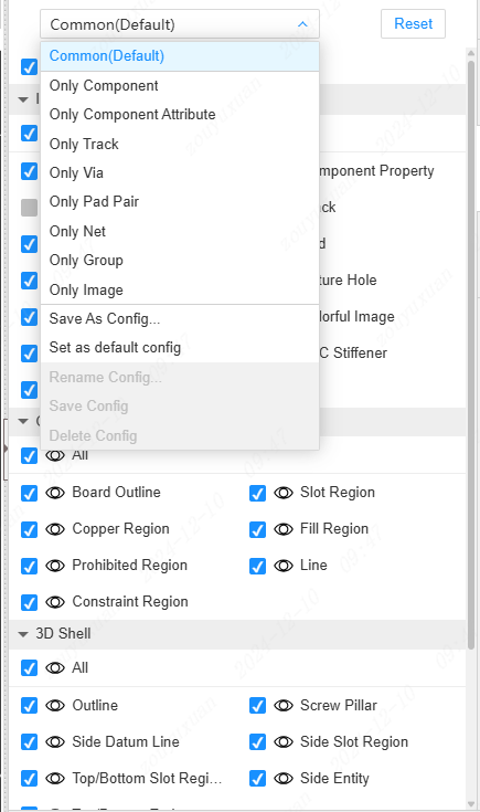
- Filtering panel supports filtering locked states and other groupings
Panels
Panel design is officially launched, support design and export production documents for production in LCSC
Experience optimizations and BUG fixes
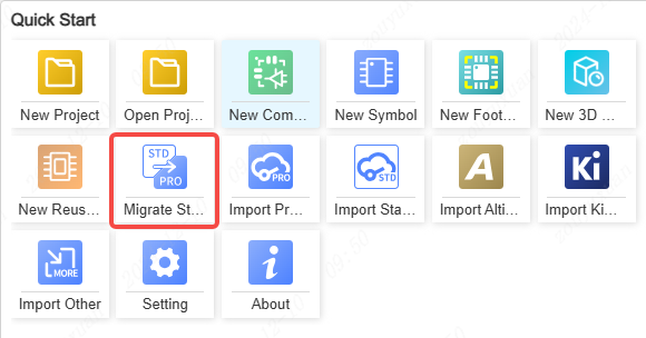
Support migrating standard projects and libraries
Others
- Support migrating standard projects and libraries

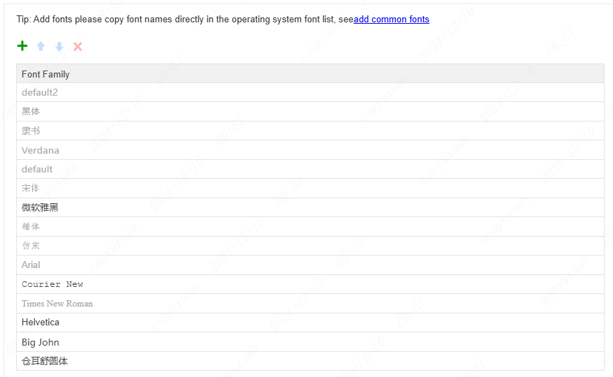
- Minify the list of default fonts and remove redundant fonts in Settings, Fonts and Restore Defaults.
Open the copied URL to open the corresponding document
Editing the same project on a different computer will cause the document label on the other computer to change color and prompt changes
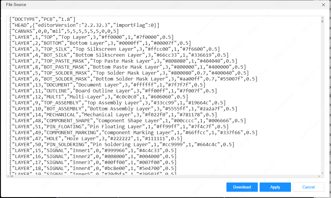
Support applying the document after modifying the source code
- Import the Pro project support extract library
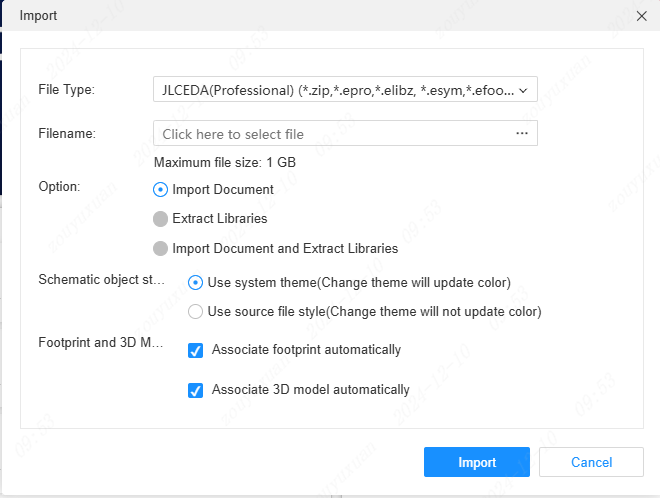
Support logging output exception handling items when importing other EDA files
The exported EasyEDAPro Professional document is added with the corresponding EasyEDA Pro suffix, beginning with e. 'efoo, esym, epan, epcb, esch, eprj' (for the client)
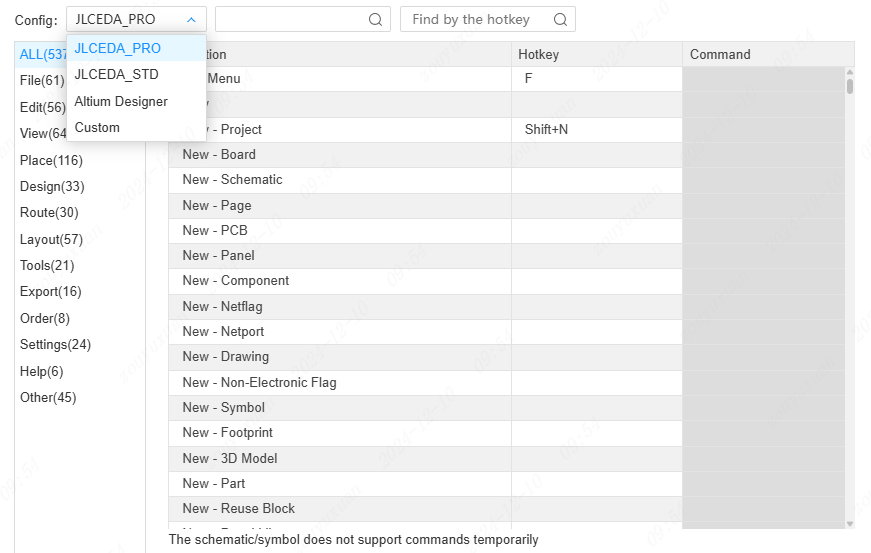
Support keyboard shortcuts for configuration switching
- Fix some bugs and optimize some details